Description
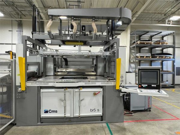
CMS BR5 1512S – Year 2020
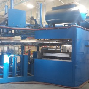
Thermoforming Heavy Duty Vacuum Former Machine
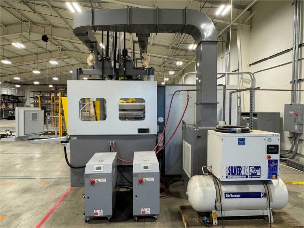
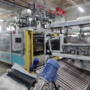
2020 CMS “BR5-1512S” Heavy Duty Vacuum Former
The BR5 model is a vacuum forming machine that produces top quality parts out of thermoplastic sheets
up to 10mm thick. With unmatched quality and reliability, the BR5 will ensure maximum productivity
with an easy to use HMI (human machine interface). The BR5 is equipped with multiple solutions for
sheet heating, mould changing, sheet management and cooling capabilities
Max sheet size mm/in 1.560 X 1.260, 61.4” x 49.6”
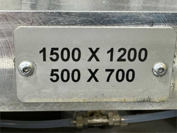
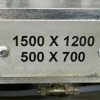
Maximum lower frame size mm/in 1.500 X 1.200, 59.0”x 47.2”
Minimum lower frame size mm/in 500 X 700, 19.6”x 27.5”
Max mould height mm/in 600, 23.6”
Upper heater power kW 97
Lower heater power kW 97
Vacuum pump rate mc/h 1 X 100
Total power installed kW 220
Compressed air pressure Bar 6
Power supplyV 400
phases 3+N(TT or TN-S)+T
Noise level Db(A) Leq 73
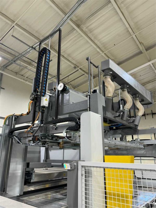
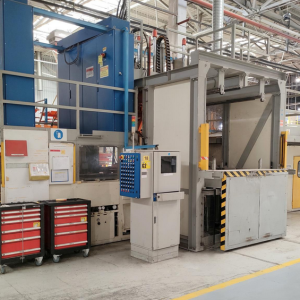
AUTOMATIC SHEET LOADER AND PART UNLOADER
This system allows the operator to load and unload the sheet material both prior to the thermoform
process and following part completion. The auto-center and management function will automatically
move the sheet into proper orientation before advancing the sheet into the thermoform station. The
loading trolling is controlled with vision and operated using high quality servo motors.
Loader Positioning : Left
NEW Sheet centering device
The automtic sheet centering system mechanically aligns sheets prior to loading
to ensure proper orientation in the machine. The Length of the sheet is
measured using an optical sensor during the loading process to align the sheet
perfectly for the thermoforming process. Access to the loading area is allowed
during a work cycle enabling the operator to load and unload without stopping
production.
PLUG ASSIST
Advanced plug assit uses brushless servo motors allowing operator control of feed speed through the
control interface. System allows storage of parameters to ensure accurate and repeatable assist.
System is equipped with an electromagnetic brake and security system that locks motion of positioning
axis in case of ESTOP or powerloss.
TOOTHED BLADE – 100% PARAMETER SHEET CLAMPING
Optimal clamping is achieved between the plate and frame with a toothed
blade and sealing gasket. This system ensures the sheet is completely
secured during the thermoforming process.
AUTOMATIC ADJUSTMENT OF CLAMP FRAME DIMENSION
(LONGITUDINAL BEAMS CENTER DISTANCE AND TELESCOPIC BEAMS)
The frame is made of heavy gauge steel to maintain its rigidity. Using
brushless servo motors the frame size adjust to the proper dimensions.
This system allows for more flexibility with mould design and sheet
management. When the sheet thickness varies, no adjustment is required.
Servomotors control the clamp frame dimension continuously. The control
cycle is automatic and can be saved in programs.
AUTOMATIC WINDOW FRAME (REDUCTION STROKES X-1000
MM, Y-500 MM)
The automatic window frame allows the flexibility in the thermoforming
process. Dimensions are controllable up to 1000mm in X and 500mm
in Y.
The window plate is made of aluminium and it is complete with copper
pipes inserted into the plates for complete thermostatic control.
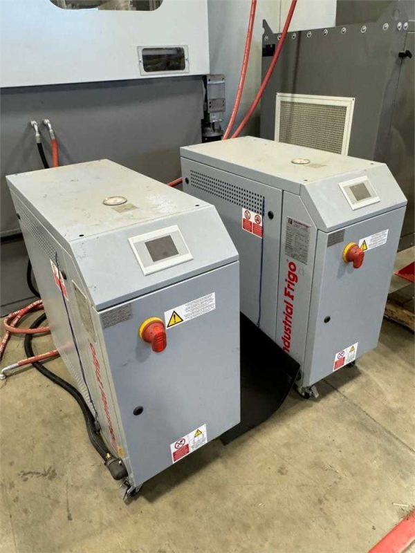
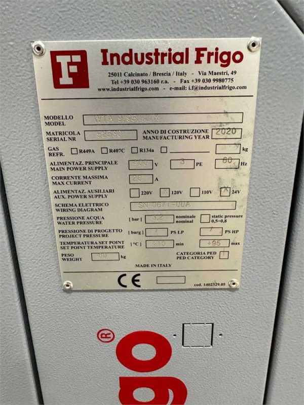
THERMOREGULATOR REDUCTION PLATE
Thermoregulator unit controls temperature of Plate up to 95 degree C using water.
AUTOMATIC HEATER MOVEMENT BY SERVOMOTOR
Heating elements are managed with two servomotors creating a “reciprocating” motion (patented)
designed for optimal heat distribution on the entire surface of the sheet. Motors are backed up with a
battery set to safely move the heaters into the start position in the event of a power loss.
HALOGEN LAMPS (SPEEDIUM)
The heaters are equipped with halogen lamps (800/300 W),
controlled individually both in percentage and in power, which allow
to reduce heating times and to maintain a low temperature while the
machine is working; thereby the productivity increases.
The heating elements are wired with nickel cables.
GLASS-CERAMIC COVER
Bottom heater is equipped with glass-ceramic covers.
OPTICAL PYROMETER
The optical pyrometer controls the sheet temperature.
MOULD PLATE
The mould plate is equipped to control the temperature of the mould with no. 2
plugs. The movement of the plate is managed with an electronic gantry by means
of two servomotors.
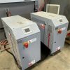
THERMOREGULATOR BY WATER FOR MOLD
Thermoregulator by water with high cooling capacity. Heating power: 9 kW/280°F
QUICK MOULD CHANGE SYSTEM
The quick mould change system provides the operator a quick and easy way to change the mould to
maximize production and minimize change over time. The plate is easily removable by a mechanical lifting
system inside the machine structure. Once fully lifted for extraction a trolley is locked into place and the
operator can easily slide the mould plate onto the trolley by way of roller bearings on the trolley. Once the
mould is removed and a new mould plate is introduced to the machine it is automatically centered.
TROLLEY EQUIPPED WITH PNEUMATIC MOULD LIFTING SYSTEM
The mould trolley is equipped with a pneumatic system which lifts up the mould
by four screws (pneumatically controlled) in order to allow load and removal
of trolley by forklift.
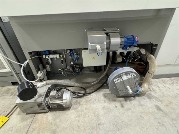
VACUUM PUMP 165 MC/H CAPACITY
The system consists of two oil blade pump (165 mc/h each).
Vacuum and vacuum management is equipped with three modes in order to
achieve proper cycles and quality.
FORMED PART COOLING
Centralized Formed Part Cooling
Formed part cooling occurs by high capacity and adjustable (in all the directions)
draw holes.
A big fan installed on the floor supply the air at the draw holes.
PYROMETER FOR FORMED PART COOLING CONTROL
Positioned on the machine, above the part, the pyrometer takes thermal
readings of the thermoformed part and controls the temperature during the
cooling process.
PROPORTIONAL SYSTEM
Both vacuum and air flow functions are controlled by proportional valves. These
valves allow for continuous control of pressure and flow rate. The values are
saved for future part programming.
The pressure chamber for managing pre-stretch is operated by an electro
fan and not compressed air. The controllable electro fan allows for better
air volume management.
SENSOR FOR PRE-STRETCH BUBBLE CONTROL
The photocell measures the pre-strech bubble height allowing the controls to
automatically optimize airflow. Pre-Stretch optimal height can be fixed at set up and
managed automatically by way of the photocell.
SHEET SAG CONTROL
The pressure system, airflow, optical photocell and heating elements work together to create “Zero Sag”
during the heating phase. Zero Sag allows for the highest quality of thermoformed parts.
SHEET SAG SAFETY SYSTEM
An emergency photocell (laser), fixed on the machine body, ensures the lower
heater safety.
An emergency photocell, fixed on the movable frame above the transversal
bars, ensures the upper heater safety.
MACHINE BODY COOLING
An automatic exhauster allows the machine frame to be cooled at the same
time the mould cooling is in process. In this way machine distortions and mould
overheating are avoided.
FRONTAL DOORS
Frontal doors provide a barrier for protection and also make mold
management very easy. The doors are equipped with proximity switches to
ensure operator safety during production.
SAFETY
A laser curtain is installed in front of the machine and is equipped with lateral covers for
both laser and operator safety. All other access doors are also equipped with proximity
switches for operator safety.
PLC AND CONTROL SYSTEM
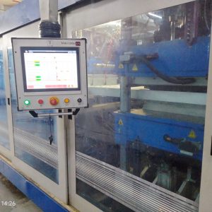
The machine is managed by a PLC controller and touch screen interface. All elements of the Thermo
process can be addressed from the control panel. The system allows for heating parameter storage in
order to reduce the reoccurence of errors. The storage is possible on both hard disk or USB. Diagnostic
features allow operator to see any anomalies in the cycle visually on the control panel. The operator
inteface also allows for the operator to run a complete manual cycle.
The system allows for online access for trouble shooting by a CMS technician via
the 24hr hotlineand comes standard with Industry 4.0 capabilities to ensure proper
management visibility into the production process.
ELECTRICAL CABINET
A separate electrical cabinet in rigid anodized aluminum structure is located beside
the machine, dust insulated, in which all the main electrical and electronic parts for
the machine control are installed. Protection level: IP 54.
An air conditioning system keeps the internal temperature below 35 degrees C (95
degrees F.) The electrical cabinet is located on the right side of the machine
with respect to the loading position, unless otherwise noted under the included
equipment section.
OPC-UA
Machine connectivity using Industry 4.0 standard OPC-UA protocol makes it possible to read process
parameters, machine status, alarms and productivity values.
OPC-UA also allows real-time messages to be sent to operator(s) to optimize production capacity.
INSTALLATION DATA
All CMS machines adopt the neutral wire connection to avoid any electrocution risk for the operator.
Voltage: 480 volts, 3 phases, 60 Hz. (or as specified by the customer). The voltage specified must be
within +5% to –5% of the nominal line voltage.
The machine is supplied with a UL transformer with the primary voltage as specified by the customer and
the secondary voltage of 400 volts, 3 phases. 60 Hz.
The machine can be connected (either directly or by means of a transformer) to the TN (TN-C; TN-S)
supply systems.
If not, the customer shall provide for a secondary, earthed star-to star transformer, placed on line (before)
the machine control board.
Since the electrical board contains equipment that may generate a continuous component of the fault
current, we suggest to use a delayed-action (selective) device type A, or better type B if available, with 0.3
A adjustable differential current, for differential protection (not compulsory for the machine).
MACHINE COLORS
CMS standard colors: Light Grey RAL 7035 and Dust Grey RAL 7037
MACHINE COMPLYING WITH CE STANDARDS
The machine complies with the applicable parts of the following Directives:
Directive 2006/42/CE
Directive 2014/30/EU
CMS machines are designed and manufactured in compliance with the European Directives cited in the
Conformity Certificate released with the machine documentation.
The User’s and Maintenance manual is the cornerstone for all information related to machine use and
maintenance, and therefore to the operators’ safety. For this reason, the customer shall acquaint himself
with the various chapters (among which Allowed Usage, Residual Risks, etc.)
In case of machines bound for the American market please note what follows:
From the electrical point of view the CE adopts the European and international ISO EN 60204-1
regulation, that mostly differs from the corresponding UL, CSA;
From the visual warning point of view, the CE does not accept the usage of warning signs, but
the content of the User’s and Maintenance Manual applies.
The CE conformity certificate testifies CMS’, the supplier’s, “good faith” to comply with European legally
binding laws.
Checking the regulations in force in non-European countries is the customer’s liability.
CMS thermoforming machine BR5 Special Spa
The thermoforming machine BR5 Special Spa has great potential, especially when thermoforming large workpieces such as the production of wellness spas. Changing the mold, placing the plate and removing the formed component are all done conveniently and ergonomically outside the machine. Manual loading can be supplemented by a semi-automatic handling system if required. The BR5 Special Spa offers a number of technical advantages, such as an optional second vacuum circuit for forming the tub edge.
Thermoforming machine for manual or semi-automatic loading of large plates (e.g. for the production of whirlpools) in front of the machine.
For plate formats from 2,500 x 2,500 mm to 6,000 x 2,500 mm
