Description
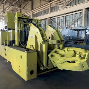
NEC National Electrostatics Corp. Pelletron Particle Accelerator ANCORE Tandem 10.5SDH-4 PFNA
National Electrostatics Corp. (NEC) provides industry-leading electrostatic ion beam accelerator systems and related components designed to expand the research goals of scientific and technical communities around the world. NEC’s complete IBA systems provide a fast, thorough, and verified materials analysis answer to unknown targets. The key components of an NEC accelerator system are contained in the pressure vessel, often referred to as the Pelletron or tank.
These components include: a charging system, acceleration tubes, a column/support structure, and either a gas/foil stripper (tandem) or an ion source (single-ended). The Pelletron is pressurized with SF6 insulating gas and includes a recirculation system to keep the SF6 gas clean and dry. A gas handling system is included to assist with the transfer of the SF6 gas to a storage system when necessary.
Pelletron IBA System Features
Measures multiple techniques simultaneously
Generates composition vs. depth resolution information
Provides elemental sensitivity up to PPM levels
Provides depth resolution up to 100 angstroms
Automates data collection and analysis
Designed for unattended operation with a complete interlock system
IBA Applications: Radiation damage, Nuclear physics, Biology, Material science, Environmental science, Art science, Archaeology,
Geophysics, Medicine, Forensics science, and many more …
Pressure Vessels
The size of the Pelletron is dependent on the terminal voltage of the system, the type of column/support structure, and whether it is a tandem or single-ended accelerator. The Pelletron and SF6 recirculation systems conform to local or international codes including
ASME, CE, and additional standards. The pressure vessel is rated at 125 psig internal pressure and 15 psig external pressure. There are ports on the pressure vessel for components such as generating voltmeters, capacitive pickups, corona probes, electrical feedthroughs, and windows. Accelerators up to about 4 MV usually have two sections of the tank: the bell section and the end plate. The accelerator column is attached to the end plate. The two sections can be separated for access to the column for maintenance.
Charging Systems
The Pelletron charging system is a core part of NEC’s accelerator technology, due mainly to the unique Pelletron charging chain.
The chain was developed in the mid-1960s as a significant improvement over the Van de Graaff charging belt. The chain is made of metal “pellets” that are connected by insulating nylon links and has proven to achieve superior terminal voltage stability and exceptional durability. Chains can last as long as a decade or more before needing replacement.
Though other charging systems, such as solid state systems, have also been designed to replace the belt, the Pelletron charging system has consistently demonstrated equivalent performance, while allowing for quick and simple repairs when needed. The Pelletron charging system has been used in the world’s largest electrostatic accelerators, achieving over 30 MV in tests.
Pelletron Chain System Method:
Exceptional durability with no electronic components in the accelerator
Immune to spark damage
Short down time (a few hours) to replace system components
Modular design with straightforward troubleshooting and maintenance
Used in accelerators up to 30 MV terminal voltage
Pelletron Charging System Features:
Excellent voltage stability
High efficiency
Isolation from line voltage ripple
No electronic diagnostic equipment required
Simple and reliable
Long life
Proven to over 30 MV
Charging System Performance
Current to HV terminal: 100-200 μA per chain depending on particular design
Current on target: 25 μA or more of beam per chain depending on configuration
Systems can be equipped with 1 to 8 chains depending on charging currents required
Pelletron Charging System Method
The metal pellets of the Pelletron chain are charged by an induction scheme. For a positive terminal, the negatively-charged inductor electrode (connected to an external power supply) draws positive charge into the pellets while they are in contact with the grounded drive pulley. There is no charge transfer from the inductor electrode to the chain.
Since the pellets are still inside the inductor field as they leave the pulley, they retain a net positive charge.
The chain transports this charge to the high-voltage terminal.
When the pellet reaches the terminal, it passes through a negatively-biased suppressor electrode. This prevents arcing as the pellets approach the terminal pulley.
As the pellets leave the suppressor, the charge flows smoothly onto the terminal pulley, giving the terminal a net positive charge. This process is commonly referred to as “up-charging.” There is no charge transfer from the suppressor electrode to the chain.
Most Pelletrons employ “down-charging” as well. Down-charging works identically to up-charging, except the inductor/suppressor polarities are reversed, and it effectively doubles the charging current capacity of the chain. Inductor/suppressor electrode voltages are provided by terminal power supplies and match drive end voltages via fiber optic signals.
Pickoff pulleys can also be used by drawing a tiny amount of charge from the chain. This technique allows down-charging without the use of HV supplies in the terminal.
Acceleration Tubes
NEC’s all metal and ceramic acceleration tube assemblies are ideal for applications that require ultra-high vacuum capability in regions of high voltage or where a complete insulating barrier is required. The tubes are either metal brazed or bonded assemblies with no organic compounds.
The special bonding method is one reason NEC acceleration tubes are so durable – some being in use on a routine basis in very strenuous conditions for periods of over 40 years with no signs of degradation. In addition, all NEC tubes are insensitive to thermal shock and exhibit exceptional mechanical strength.
NEC offers two different styles of acceleration tubes based on application:
General Purpose Acceleration Tube – for use in ambient air conditions
High Gradient Acceleration Tube – for use in 80 psig SF6 insulating gas
General Purpose Acceleration Tubes
The General Purpose (GP) Acceleration Tube is designed for operation in clean, dry ambient air and is in use on all NEC open-air ion beam systems up to 500 kV and ion source injectors.
The all-metal and ceramic GP Acceleration Tube section is a metal brazed assembly with no organic compounds in the vacuum volume. This tube is bakeable up to 500° for contaminant-free and ultra-high vacuum operation.
Each section is conservatively rated at 75 kV. Multiple sections can be combined to achieve higher voltage. The exterior field is defined by removable potential distribution rings. Potential grading is typically provided by ten 150 MOhm resistors in series.
A non-magnetic version of the General Purpose Acceleration Tube is also available for the acceleration of low energy electron beams that are adversely affected by proximity of magnetic materials.
General Purpose Tube Features
Designed for accelerating intense beams of heavy and light ions
Conservatively rated at 75 kV per section
Used on open-air ion beam systems up to 500 kV
Modular design for easy and quick replacement/refurbishment of individual sections
Column and Support Structure
NEC uses two distinct support structure designs: the U-Series and S-Series. The usage depends on the application, the configuration, and the type of ion source if single ended. Both the U-series and the S-series can be built in tandem or single-ended configurations. If needed, individual sections of acceleration tubes can be accessed and repaired or replaced without the need to disassemble the complete structure. This allows for fast replacement time and short down time.
U-Series
The column structure for a U-series system is divided into 1 MV sections. These sections are supported by insulating ceramic posts and have unparalleled strength and durability. The posts are then connected to bulkheads that hold the acceleration tube. This design is used for some horizontal single-ended systems that have large terminals with quite substantial ion sources. The U-series design is also used for all vertical systems.
S-Series
The S-series column is composed of parallel acrylic plates surrounded by equipotential rings. The acceleration tube is held inside the acrylic plates, which are supported on both sides of the tandem by large bulkheads and by the terminal in the middle. The S-series design is mostly used in horizontal tandem accelerators 6 MV and below, and single-ended accelerators with a lightweight ion source.
Both S-Series and U-Series Pelletrons can either be in Single-ended or Tandem (dual acceleration) formats. In both cases, ion beams (both positive and negative) are accelerated by an electrostatic field, i.e. a potential drop, resulting in a true DC beam.
Tandem
Tandem accelerators have both ends of the Pelletron at ground potential, with the high-voltage terminal in the middle. Negatively-charged ions produced by an NEC ion source are accelerated to the terminal. Inside the terminal is a stripper, which uses a gas (usually N2, Ar, or He) or a thin carbon foil to remove electrons from the incoming negative ions. The now positively-charged ions experience a second boost of acceleration (hence the name “tandem”) as they exit the terminal and travel through the acceleration tube to ground at the high-energy end of the Pelletron.
Single-ended
Single-ended systems have the high-voltage terminal at one end of the accelerator tube and a positive ion source, such as a Positive RF source, inside the terminal. The exit of the Pelletron is at ground potential, where the ion beam emerges with an energy equivalent to the terminal voltage plus source potential.
Gas/Foil Stripper
Tandem Pelletrons use one of two types of electron strippers – gas or foil – to convert the negative ions entering the terminal into positive ions.
Gas Stripper
In a gas stripper, argon or nitrogen gas is supplied to the terminal. A metering valve is provided to meter gas to the stripper canal. One to three turbo-molecular pumps are used in the terminal to recirculate the stripper gas to allow only a small amount of gas to flow into the acceleration tubes. The stripper tube length is designed for stripping of the ions beyond equilibrium. Such stripping is necessary to effectively reduce the hydrocarbon molecules in the ion beam.
Foil Stripper
Thin carbon foils are often used in place of, or in addition to, gas stripping.
Gas Recirculation Systems
The pressure vessels of Pelletrons are designed to be filled with about 80 psig of Sulfur Hexafluoride (SF6) as an insulating gas. The gas is recirculated, being dried and filtered in the process. If the pressure vessel needs to be opened for maintenance, the SF6 gas must be transferred out of the vessel first, as it should not be released into the environment.
The SF6 gas recirculation system is mounted on the accelerator tank. It includes an axial blower, a dryer section filled with alumina desiccant beads, a filter, and a heat exchanger. The blower draws SF6 from the top of the tank, where the gas then passes through the dryer, filter, and cooling sections. The recirculation system then returns the gas near the bottom of the tank.
A port on the recirculation system is used to connect to a gas handling system. When needing to remove SF6 from the tank, the gas handling system will remove air from the storage tank and remove the SF6 from the pressure vessel, liquefying it for storage in a storage tank. The gas handling system can then fill the pressure vessel with SF6 from the liquid storage.
CONDITION: Used. In excellent condition. Complete system intact. Professionally de-installed. Upgrade, Refurbishment, and Re installation available


