Description
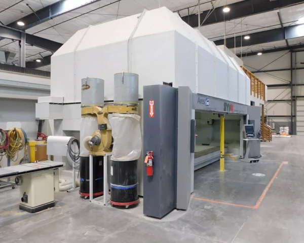
CMS ARES 60/26-PX5 CNC Monoblock 5-Axis Router Machining Center – Year 2014
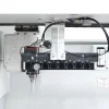
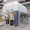
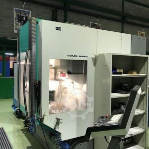
CMS type ARES-6026-PX5 machining center
CNC machining center designed for high speed machining of a large range of materials
including aluminum, other light alloys, composite materials, reinforced plastics, tooling
board, and wood.
Structure……………………………………………..
Monoblock with moving bridge
Axes Strokes Quick Positioning Speeds
Linear X = 6,000 mm (236.22″) 80,000 mm /min. (3149.6″/min.)
Y = 2,600 mm (102.36″) 80,000 mm /min. (3149.6″/min.)
Z = 1,200 mm (47.27″) 70,000 mm /min. (2755.9″/min.)
Rotating B = +/- 120 degrees 9,000 degrees /min.
C = +/- 270 degrees 9,000 degrees /min.
Working Area………………………………………………
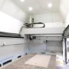
One steel work table, 6,070 mm x 2,355 mm (238.97″ x 92.71″)
One vacuum table, 6,040 mm x 2,365 mm (237.79” x 93.11”)
Tilting central support post on the front of the machine
Working Unit………………………………………………
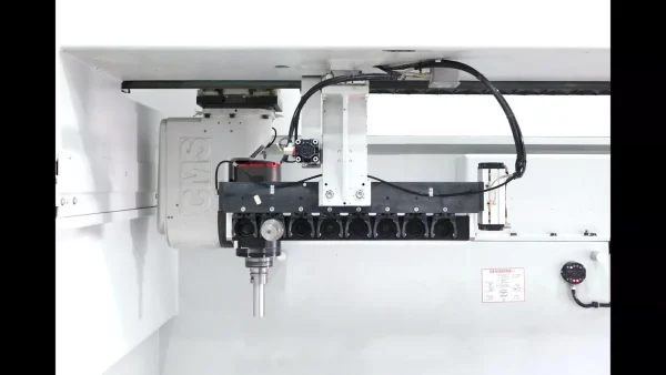
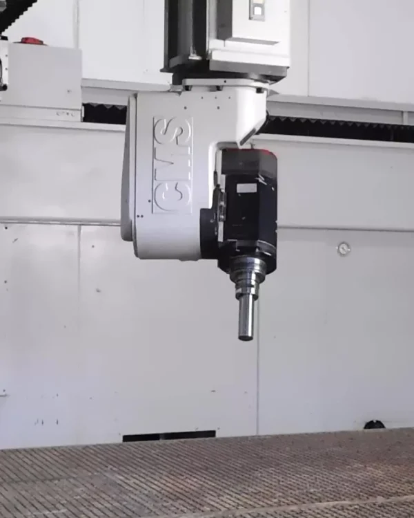
One head, type PX5, with liquid-cooled electrospindle
Power: 15 kW (20.1 HP) at 12,000 rpm, maximum speed: 24,000 rpm
The machine is equipped with one eight-place toolchanging magazine
Static Frequency Converter
One frequency converter with rotation speed from 1,000 to 24,000 rpm
Numerical Control…………………………………………..
FANUC 31i-B5
Vacuum Plant
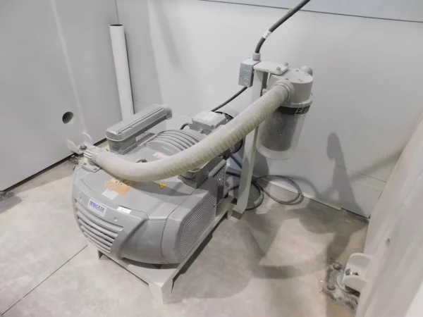
Two 250 cubic meters per hour dry vacuum pumps
Machining Center Description
CMS type: ARES-6026-PX5 Machining Center
Structure and Carriage Movements
CNC machining center with a fixed
working plane and moving bridge.
The machine base is made of thick,
welded, stabilized steel, designed for
strength and rigidity. The X axis
movement is carried out by a moving
bridge. The Y axis transversal
movement is carried out by a
carriage moving on the bridge. The Z
axis carriage, vertical movement, is
mounted on the X axis carriage.
The carriages move via four-way
recirculating ball track bearings on
large cross section, interchangeable, inserted guide ways (STAR Type) that are
hardened and ground.
Axis movement is controlled by AC brushless servomotors.
The movement of each axis takes place with a hardened and ground precision rack in
which a precision pinion meshes.
Tilting central post on the front of the machine.
The X and Y axes guides are supplied with bellows covers.
The Z axis guides are supplied with double scrapers.
Working Area
The machine has a welded steel
working table with threaded holes
in a pattern of 600 mm x 300 mm
(23.62” x 11.81”) for attaching
fixtures.
The table has hoppers around the
internal sides of the table making
the collection and removal of chips
easier and is predisposed for a
suction system on the back of the table.
Mounted on top of the steel working table is a
vacuum table for clamping pieces in work. The
surface is milled in a grid pattern for roundsectioned
gaskets that can be inserted into the
table grooving to delimit the vacuum area to be
used. Arranged on this grid pattern are threaded
holes with bushing. These holes can be used
either to create a passage for the vacuum from
the vacuum chamber located on the bottom of
the table to the surface of the table or for
clamping spoil boards and various fixtures. The
vacuum is sealed off from the surface by a bolt with an O-ring.
The vacuum table has a working height of 530 mm (20.87”) from the floor.
Working Unit
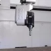
Working Unit type “PX5”.
The head is equipped with two NC controlled rotating
axes, the fourth and fifth axis, allowing the head to be
rotated in any direction.
The axes are moved by AC motors coupled with high
precision reduction units.
The head is equipped with a special spindle with
bearings designed for high rotation speeds.
The electrospindle is cooled by a liquid refrigeration
system that recirculates the coolant.
The electrospindle is equipped with automatic
toolchanging ability with a HSK 63E connection that
works with an eight-place toolchanging rack mounted
under the center of the X axis.
The PX5 working unit is equipped with
pneumatic brakes for clamping the B and C
axes in a fixed position. This allows an
increase in rigidity during machining that
does not require the interpolation of the B
and C axes.
Tool blowing device.
The static frequency converter constantly
regulates the speed and the rotational direction of the electrospindle.
A dust collection hose from the back of the machine to the PX5 working unit is
supplied.
Mist lubrication unit with 6.5-liter (1.7-gallon) pressurized tank.
Electrospindle Characteristics
Power 15 kW (20.1 HP) at 12,000 rpm / S1
19 kW (25.4 HP) at 12,000 rpm / S6 40%
Maximum revolution speed 24,000 rpm
Internal Cooling By liquid
Tool cooling Air pressure or coolant – from external hose
Connection shaft HSK 63F
Torque 12.1 Nm (8.9 foot-pounds) / S1
15.4 Nm (11.3 foot-pounds) / S6 40%
Bearing type Ceramic (front-back)
Spindle bearings lubrication By long life grease
Distance from pivot point to spindle nose 165 mm (6.50”)
Numerical Control
FANUC 31i-B5 numerical control with PC Office
integrated in the electrical cabinet.
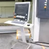
Operator controls with 17” monitor mounted on a
moveable pedestal.
Main features:
CPU Card B2, DRAM 128 MB/High-Speed CPU
FROM/SRAM Memory P, 128 MB / 2 MB
PROFIBUS DP Interface Board, Master
Dual Check Safety
High-Speed Smooth TCP
(Tool Center Point Control)
Quick program restart
Helical Interpolation
Bell-Shaped Acceleration/Deceleration after Cutting Feed Interpolation
Programmable Mirror Image
Scaling
Coordinate System Rotation
Multi Part Program Editing
Machining Condition Selection Function
3-Dimensional Cutter Compensation
Tilted Working Plane Indexing Command
3-Dimensional Manual Feed
Al Contour Control II
High-Speed Processing
Data input: Millimeters or Inches (as requested)
HP PC
Main features:
Processor: Intel Celeron E3400 at 2.6 GHz
1 MB of cache L2
2 GB RAM DDR3-SCRAM PC3-10600 – 1333 MHz.
Hard disk: 250 GB SATA 7200 rpm
Graphic card: Integrated Intel Graphics Media Accelerator 4500
DVD ROM
HP JB PS/2 Keyboard
Optical Scroll mouse
Lan Ethernet Gigabit Intel 82567V
6 USB 2.0, 2 PS/2, 1 RJ-45, 1 VGA
Operating System: Windows 7 – 32 bit
Remote Control
Standard FANUC – Emergenc yp ubsuht-tobnutton equipped with:
– Safety button (dead man)
– ON/OFF switch
– LCD 16 character Display on two lines
– Centesimal hand-wheel
– Feed override switch
– Keyboard with led for the following functions:
– One axis selection
– Axes “zero” selection
– Wheel mode
– Jog mode
– Positive and negative movement
– Quick speed movement
– Automatic mode
– Single block mode
– Dry run mode
– Start cycle
– Stop cycle
– Reset
– Increment selection Standard cable with length of 12 meters (39’-4”) A
Machining options:
Possibility of stopping an active program, changing the position of the linear and
rotating axes and retrieving the program from where it had been stopped (by using
the hand wheel and one axis at a time).
Possibility of stopping an active program, changing the tool length correction and
retrieving the program from where it had been stopped.
Possibility of choosing whatever block in the program and starting the machining from that
very block.
Self-adjusting cutting speed option
Tool stress dynamic control keeping the machining stress within a suitable range by
monitoring and adjusting the feed speed (the minimum and maximum speed limits must be
entered for each tool).
Remote Assistance
This diagnostic package allows CMS operators to check and modify on line machine
configurations, parameters, and programs, as well as to execute data backup operations,
therefore making remote assistance possible.
The link requires access to the internet.
Carbon Fiber Kit
The machine is equipped with additional protections against carbon fiber dust consisting of:
Additional gasket for fixing the air conditioner, the TFT video monitor frame and the
electrical cabinet base, as well as for the remote control connector.
IP65 connectors or IP65 boxes with holdfast to house the terminal boards of the machine.
Additional gaskets for the compartments housing the electrical equipments.
Sealing of:
Sheathing support plate
Sheathing connections to the electrical board and machine
Connectors on the board side, mouse and keyboard cables.
B and C Axes Re-alignment Device with Laser System
B and C axes re-alignment device with laser system for measuring tool length and diameter.
Electronic probe predisposition
The machine is predisposed for the installation of a Renishaw electronic probe.
UL Electrical Components
UL certification on the electrical components.
3D Machine File
3D machine file in PARASOLID, STEP, or IGES format, as specified by the customer.
Accessories
Eight (8) HSK 63F toolholders with ETS 32 or ETS 40 collets, type and diameters as
specified.
Two (2) groups of vacuum connections with ten
(10) connections each. One group is mounted on
each side of the working area.
Manual tool-presetting device with height gauge.
Accuracy and Repeatability Data
PLEASE NOTE: THE NUMBERS BELOW ARE ABSOLUTE NUMBERS.
Axes Stroke Positioning Accuracy Repeatability
X 6,000 mm (236.22”) 0.165 mm (0.00650”) 0.038 mm (0.00150”)
Y 2,600 mm (102.36”) 0.080 mm (0.00315”) 0.028 mm (0.00110”)
Z 1,200 mm (47.27”) 0.045 mm (0.00177”) 0.024 mm (0.00094”)
B +/- 120 degrees 60 arcseconds 25 arcseconds
C +/- 270 degrees 60 arcseconds 25 arcseconds
Accuracy of the axes tested at CMS SpA, Zogno, Italy.
Positioning Accuracy and Repeatability
CMS assures positioning precision and repeatability
according to VDI-DGQ 3441 rules. These controls are
made using LASER measuring systems. Accuracy and
Repeatability will be guaranteed with a temperature
operating condition of 20°C +/- 1° (68°F +/- 1.8°).
Auxiliary Systems
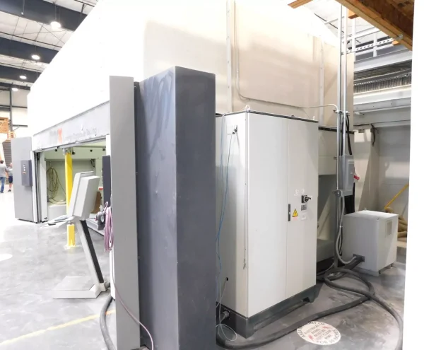
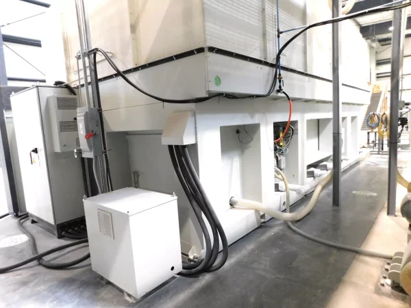
A separate dust-proof cabinet situated on the right-hand side of the machine in which
all the main electrical and electronic components for controlling the machine are
located. Protection level IP54.
The electrical control cabinet is complete with an air conditioning unit.
The machine is equipped with the standard vacuum plant for ARES machines and
includes two 250 cubic meters per hour (176 CFM at 60 Hz.) dry vacuum pumps.
Centralized compressed air system with filter assembly (to be connected to customer’s
compressed air line), pressure regulator, lubricator and minimum pressure control.
In addition to interlocking some of the auxiliary devices of the machine, this system
can control, via CNC operations, any other equipment for clamping parts, mobile
reference stops, etc.
The carriages are greased by forced injection using an automatic centralized system,
with pressure and minimum tank level monitoring.
The machining center is equipped with a push-button panel for the Start, Stop,
Vacuum ON-OFF, and Emergency functions mounted on a special support.
The machining center is equipped with automatic opening doors.
Machine complying with CE Standards
The machine complies with the applicable parts of the following Directives:
Directive 2006/42/CE
Directive 2004/108/CE
Class 3 Safety Circuits
Operator’s admittance to the machine in full safety according to EN62061 regulations
(safety PLC). Setting mode with the possibility to move the axes manually with
reduced speed through the portable keyboard with the doors opened and the
electrospindle idle.
Documentation
Manuals written in English:
One installation, use and maintenance manual on CD.
One Use and Programming manual for the numerical control on CD.
Pictographs for electrical control plate
Numerical control messages in English
Equipped With
Complete facility is available including real estate,36,000 sq ft, 5-axis machining and 90′ paint booth
