


Description
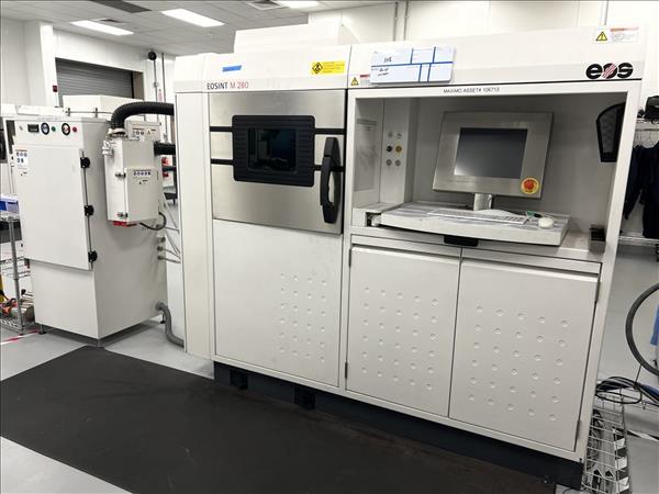
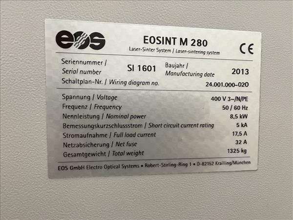
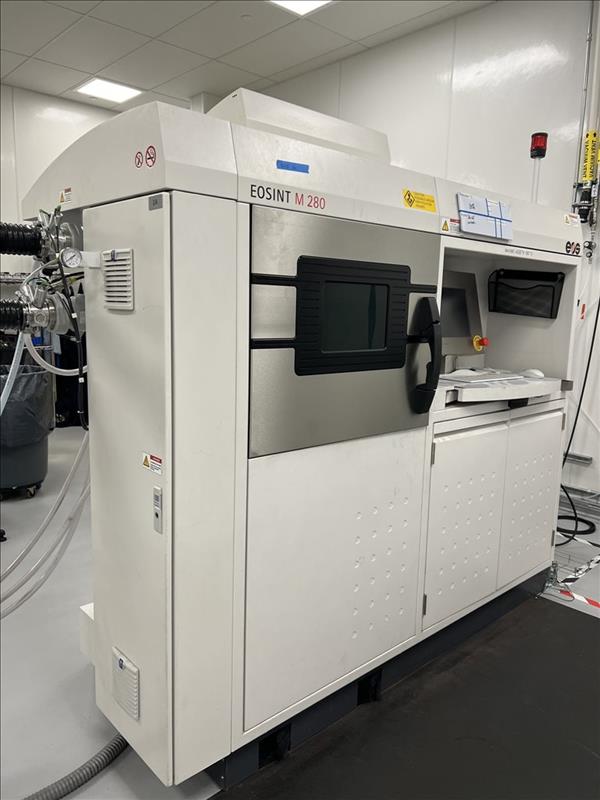
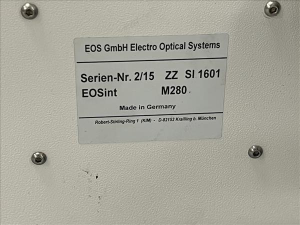
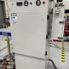
EOS EOSINT M 280 Metal 3D Printer – Year 2013
DIRECT METAL LASER SINTERING SYSTEM
Laser Output: 200W
Laser Type: Yb-Fiber
Build Volume: 9.85″ x 9.85″ x 12.8″
Scan Speed: 23′ / sec
Variable Focus Diameter: 0.004″ – 0.02″
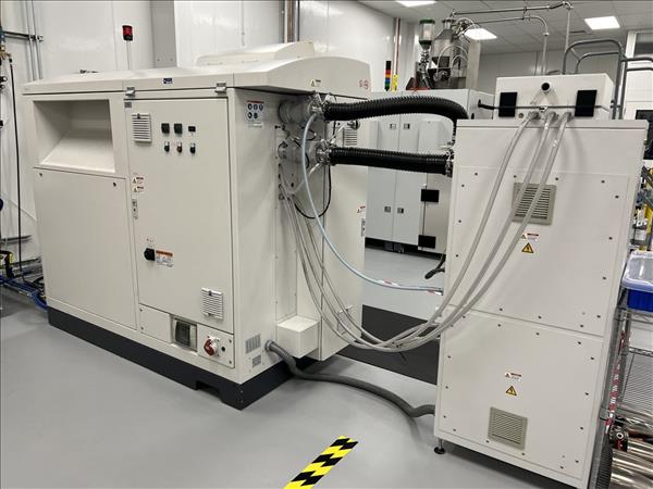
Standard / Max. Power Consumption: 3200W / 8500W
Electrical: 440V / 3ph / 32A
Compressed Air Supply: 102 PSI / 706 ft³/h
Argon Supply: 58 PSI / 3.5 ft³/min
Equipped With:
EOS RP-Tools Software
200W IPG Yb-Fiber Laser
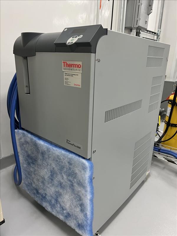
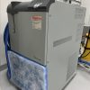
Neslab Thermo Flex 2500 Laser Chiller
DOWFROST Heat Transfer Fluid
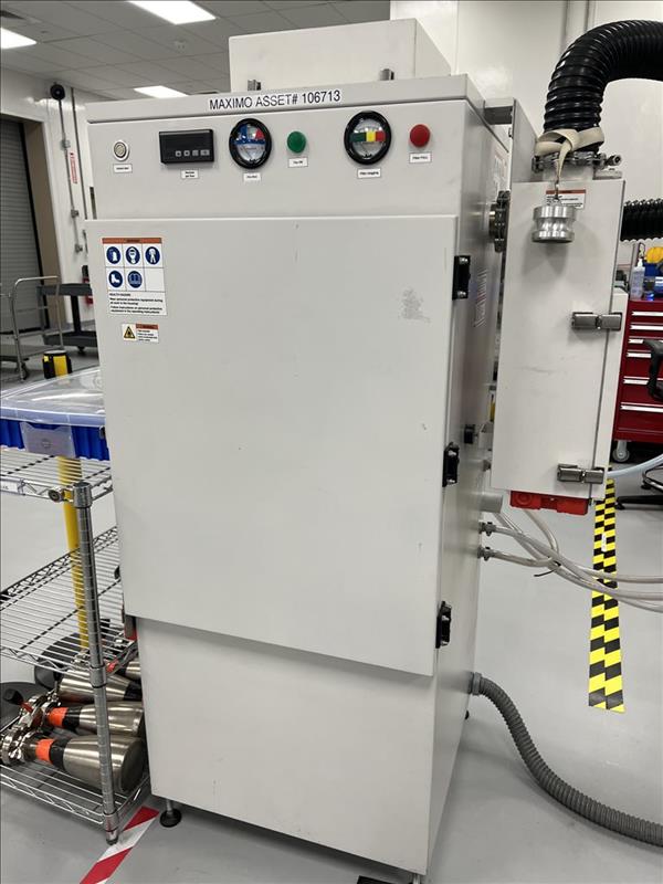
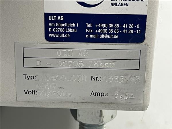
Recirculating Filter System
Exhaust Gas Filter
Transformer
Ceramic Recoater Blade
(2) Fine Particulate Filter Boxes
Suspended Particle Filter Box
Manufacturer Catalogue Information about EOS EOSINT M 280 Metal 3D Printer :
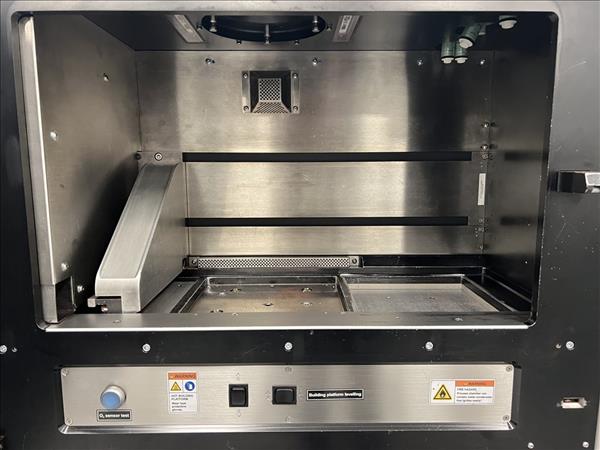
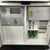
The machine comprises a process chamber with recoating system, elevating system and platform heating module, an optical system with laser, a process gas management system, a process computer with process control software, and a set of standard accessories. The machine components are integrated into a robust machine frame. During operation the process chamber is secured by interlock. Requirements of laser safety class 1 are met. When closed, the control cabinet’s specifications correspond to IP 54. The system carries the CE designation.
1.1 Basic data
- – dimensions(wxdxh)
- – weight
- – mains supply (three phase system)
- – mains fuse protection
- – maximum power consumption (incl. cooler)
- – compressed air supply
- – argon supply
- – min. argon purity: purity 99.998 % argon
2200mmx1070mmx2290mm approx. 1250 kg (without powder) 400 V +6 %/-10 % at 50/60 Hz 3 x 32 A 5.5 kW 7,000 hPa; 20 m3/h 4,000 hPa; 100 l/min Argon 4.8
Full details including required floor space, connections and environmental requirements (temperature and humidity range etc.) are given in the Installation Conditions.
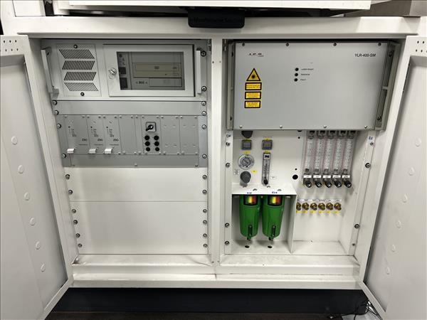
1.2 Optical system
The optical system creates and positions the laser beam to fuse (melt or otherwise solidify) the powder material. The laser emits a laser beam which is guided by an optical fibre, a beam expander optic, the scanner mirrors and a focussing objective. All optical surfaces have special coatings to guarantee effective beam guidance.
1.2.1 Laser
- – Yb (Ytterbium) fibre laser
- – wavelength
- – nominal power
1060 – 1100 nm 200 W or 400W (optional)
1.2.2 Scanner
The scanner is a high-speed scanner unit comprising precision galvanometer scanners with temperature compensation, actively cooled ultra-high reflection mirrors, integrated servo- and interface electronics, digital data transfer from the system’s control computer and digital signal processing. It also incorporates an integrated home-in sensor, which detects and corrects any scanner drift at regular intervals. A high positional stability of the laser beam is thereby maintained even under varying environmental conditions or with high thermal loading due to long exposure times and large building jobs.
- – exposure area
- – exposure speed
- – repeatability, scanner position
1.2.3 Focussing objective
250 mm x 250 mm up to 7000 mm/s < 11 μrad
The focussing objective is a so-called F-theta objective, which focuses the laser beam onto a flat field. Below the F-theta objective is a protective glass, with a pneumatic lens protection device which prevents dirt settling on the lens surface. The laser beam focus is automatically switched between two pre-defined sizes during the exposure using a dual focus system: a fine focus is typically used for accurate exposure of contours and a broader focus for fast exposure of larger areas. The sizes are manually selected according to the material being used.
- – diameter of laser beam at building area (variable) 100 – 500 μm
- – focal length of F-theta (flat-field) lens 410 mm
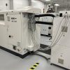
1.3 Recoating and elevating system
The recoating system creates the layers of powder. It comprises a recoating element, a recoater arm and a linear drive, which moves the recoater arm in the horizontal direction. Different options are available for the recoating element. For titanium, aluminium and nickel alloys materials a high-speed steel (HSS) blade is recommended. For other materials a wear- resistant ceramic blade is recommended.
– positioning speed 40 – 500 mm/s
The elevating system comprises dispenser, building and collector systems. The building system moves the platform carrier in the vertical direction. The part is built on a building platform which is mounted to the platform carrier.
The building platform carrier has a three-point mounting and two motorised adjustment screws for simple and exact adjustment of the platform. In combination with a measurement tool which is mounted on the recoater arm, this allows a quick and easy alignment of the platform at the start of each job. It also includes reference positioning holes for precisely and reproducibly locating build platforms with corresponding positioning holes, by means of positioning pins.
The building system has two parallel guide rails with backlash-free guides for highest positioning accuracy and long operating lifetime.
- – position repeatability ≤ ± 0.005 mm
- – maximum build height / z axis stroke 325 mm including building platform
Note: see section 3 for building platform thicknesses.
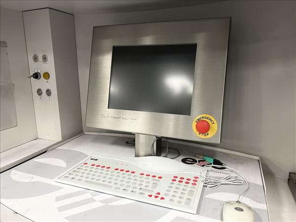
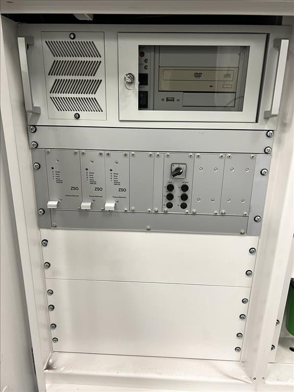
1.4 Process computer with process software
The process computer with process software (PSW) controls the build process and the system’s measuring and control components.
1.4.1 Process computer
Industrial-type PC:
- – processor
- – main memory
- – hard disk
- – monitor
- – data interface
- – other peripherals
- – operating system
at least Pentium 4 with at least 2 GHz at least 1 GB > 10 GB 15″ flat-screen LCD colour 10/100 Mbit Ethernet wipe-clean keyboard, mouse Microsoft Windows XP
1.4.2 Process software PSW
Using the process software, the building process (job) is prepared, protocolled and filed. Data can also be displayed in a graphical layer format directly on the machine with this software. It includes many features which allow the operator to obtain optimal results from the build process. Further details are available on request.
- – operating system Microsoft Windows XP
- – data input format SLI (according to EOS specifications)
1.5 Platform heating module
The platform heating module reduces temperature gradients between the building platform and the part to reduce internal stresses and ensure a good bonding of the first layers. It also removes any moisture from the powder and helps to maintain the part at a constant temperature during any interruptions in the building process to ensure maximum process reliability.
– operating temperature approx. 40 – 100 °C
1.6 Laser cooler
The laser of EOSINT M 280 requires cooling. A water-air cooler is included as standard.
– refrigerating capacity 1.4 kW
1.7 Standard accessories
A set of standard equipment for cleaning, tools for job start and removal of parts is included.