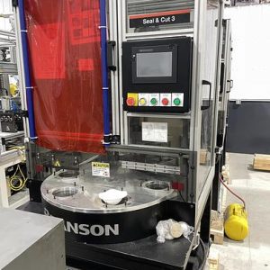
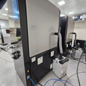
Description
Groupe TRA-C industrie Friction Stir Welding Gantry Machine for Production – Year 2022
Manufacturer: Groupe TRA-C industrie
Model: FSW friction stir welding
Year of construction: 2022
Condition: new
Functionality: fully functional
Operating hours: 15 h
Total length: 4,500 mm
Total width: 2,150 mm
Total height: 2,800 mm
Power: 15 kW (20.39 HP)
Equipment:
documentation/manual, emergency stop, type plate available
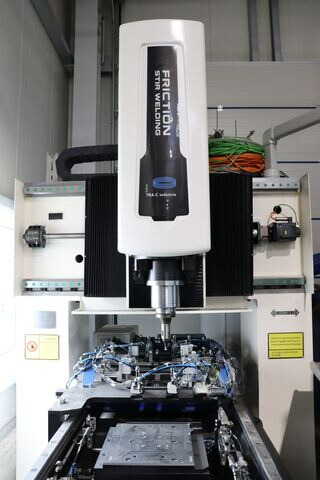
Machine FSW
– 1 welding head
– 1.6x1m working surface,
gantry-type machine.
This machine will weld the linear parts and/or 2D.
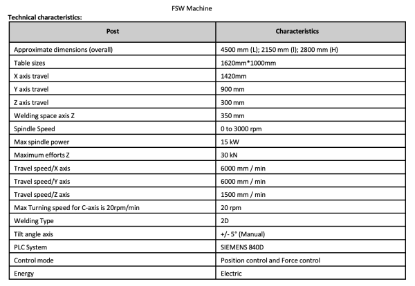
Technical characteristics:
Post Characteristics
Approximate dimensions(overall) 4500 mm (L); 2150 mm (l); 2800 mm (H)
Table sizes 1620mm*1000mm
X axis travel 1420mm
Y axis travel 900 mm
Z axis travel 300 mm
Welding space axis Z 350 mm
Spindle Speed 0 to 3000 rpm
Max spindle power 15 kW
Maximum efforts Z 30 kN
Travel speed/X axis 6000 mm / min
Travel speed/Y axis 6000 mm / min
Travel speed/Z axis 1500 mm / min
Max Turning speed for C-axis is 20rpm/min 20 rpm
Welding Type 2D
Tilt angle axis +/- 5° (Manual)
PLC System SIEMENS 840D
Controlmode Position control and Force control
Energy Electric
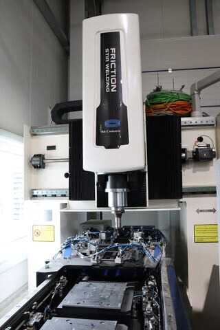
FSW machine
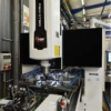
FSW machine – 1 welding head – working area 1.6 x 1 m
Gantry type machine. This machine welds linear and/or 2D parts:
FSW machine
Technical characteristics:
Post characteristics
Approximate dimensions (overall) 4500 mm (L); 2150 mm (Length); 2800 mm (H)
Table sizes 1620 mm x 1000 mm
X-axis travel 1420 mm
Y-axis travel 900 mm
Z-axis travel 300 mm
Welding area axis Z 350 mm
Spindle speed 0 to 3000 rpm
Maximum spindle power 15 kW
Maximum forces Z 30 kN
Travel speed/X-axis 6000 mm/min
Travel speed/Y-axis 6000 mm/min
Travel speed/Z-axis 1500 mm/min
Maximum rotation speed for the C-axis is 20 rpm 20 rpm
Welding type 2D
Inclination angle axis +/- 5° (manual)
PLC system SIEMENS 840D
Control mode Position control and force control
Energy Electric
Spindle torque
Spindle type: Siemens 1PH8105
The structure
The different components of the structure are manufactured using mechanical
welding assemblies and machining.
The structure consists of the following:
– A frame capable of withstanding the forces exerted by the welding head. Due to
the feedback, the machines are designed to ensure the rigidity required for FSW welding
of thick components.
– A gantry is divided into three parts: the 2 metal bars and the horizontal support to which the welding head is fixed and the SIEMENS motors drive the welding head.
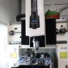
Welding head
The welding head is mounted on the gantry structure. It performs its movements in Z and Y
on guided blocks and worms of the SCHNEEBERGER brand. The head can accommodate
tools with diameters of 25 mm, 38 mm and 50 mm to change the
machine’s tool holder.
The head has a liquid cooling system to cool the tools to maintain a suitable temperature during
welding.
The welding spindle motor is of the SIEMENS brand. Description FSW head
– Power 15 kW
– 2500 rpm
– 30 kN
– Electric drive
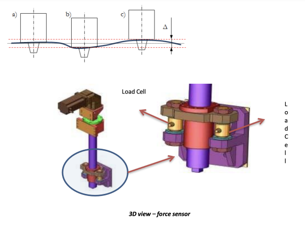
The welding head is equipped with an integrated force sensor. This sensor measures the
force exerted by the head along the Z axis. This force control regulates the force of the
head during welding. The force control controls the head rise in mm and the
speed of the head rise. To make fine adjustments, it is necessary to define additional parameters before welding:
• The welding force,
• The values for the increase or decrease of the force of the next tool (ADJ 1 and ADJ
2)
• The maximum and minimum limits that must not be exceeded
(position limit)
• Setting the force ranges (Pressure range 1 and Pressure range 2)
• The calculation cycle (ADJ period)
Load cell
Load cell
3D view – force sensor
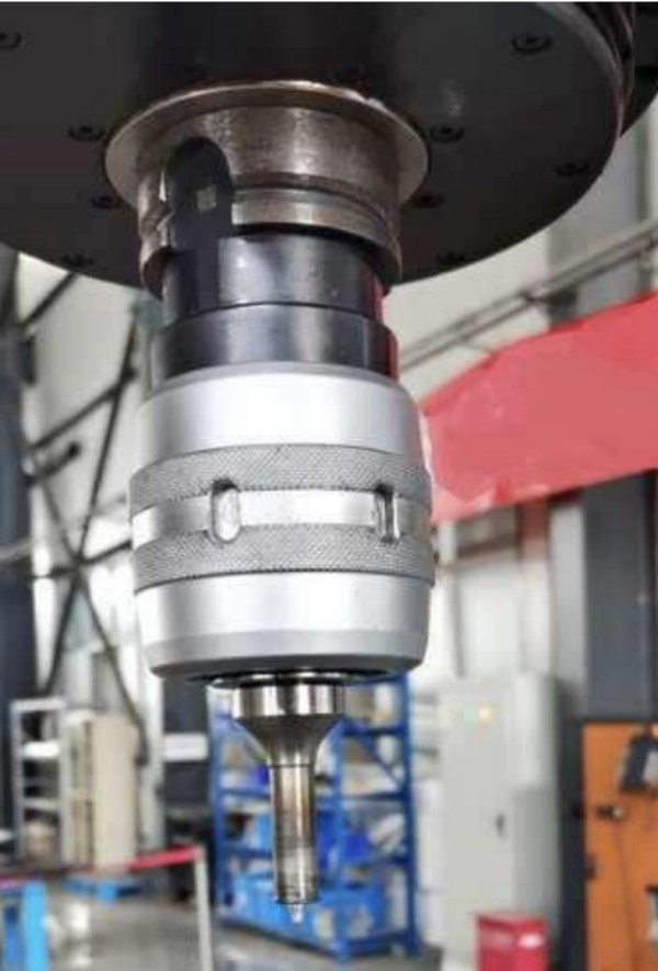
Tool holder:
Special tool attachment for quick removal and change of the FSW tool.
In this FSW model with C-axis, it is removed manually as shown in the picture:
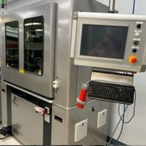
The control panel
SIEMENS 840D control panel on the FSW-M

