Description
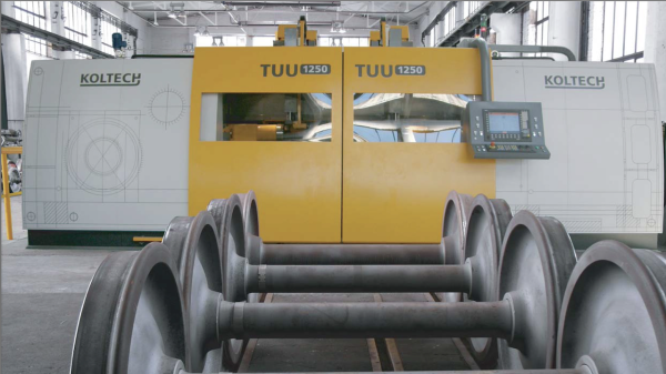
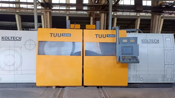
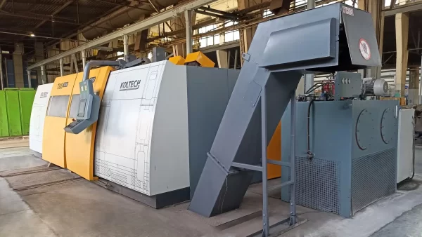
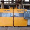
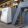
KOLTECH TUU 1250 CNC Above Floor Wheel Lathe – Year 2007
Brand : KOLTECH
Model : TUU 1250
Y.O.M.: 2007
Technical data of KOLTECH TUU 1250 CNC lathe
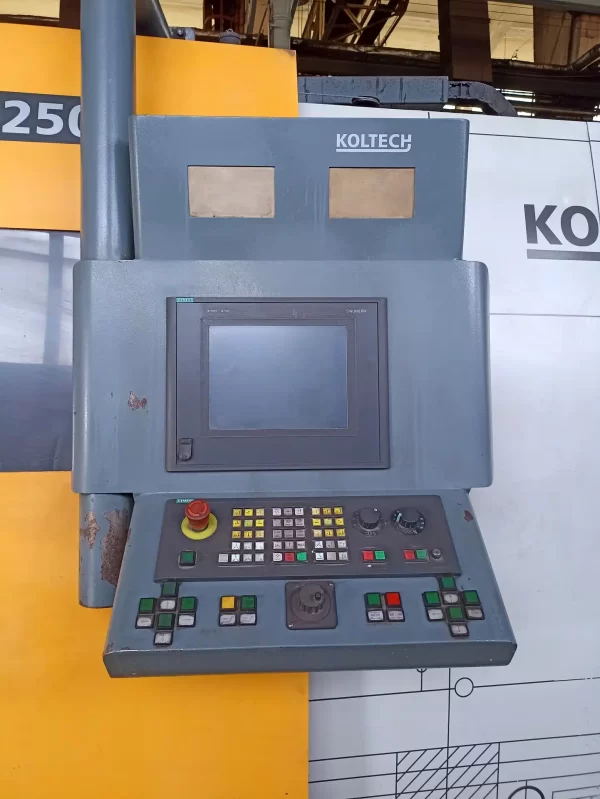
CNC control: SIEMENS SINUMERIK
maximum wheelset weight: 4 t (40 kN)
track width: 1435 mm and 1520 mm
working feed range: 0.01-2.5 mm/rev
cutting speed (stepless): 30-120 m/min
maximum wheel rolling diameter: 1250 mm
minimum wheel rolling diameter: 700 mm
maximum wheel rim width: 150 mm
minimum wheel rim width: 110 mm
maximum axle length: 2600 mm
minimum axle length: 1900 mm
power: 100 kW
power supply: 3x 400 V
dimensions (L x W x H): 5400 x 2250 x 3750 mm
TUU 1250 machine weight: 20000 kg
Together with the wheelset machine, two additional wheelsets are offered for calibration.
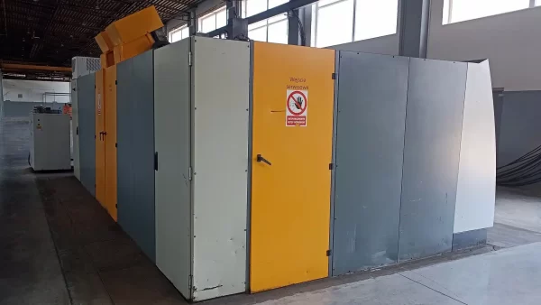
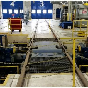
KOLTECH TUU 1250 CNC above floor wheel lathe was manufactured in Poland in 2007. The wheel lathe is a special-purpose machine designed for the turning process of the running profile of wheelsets used in various types of rail vehicles. The lathe uses high-end components to guarantee efficient and precise machining of both used and new wheelsets for the railway industry. The solidly constructed structure with friction drive allows a wheelset with a maximum weight of 4 tonnes to be fed into and out of the machine from hall level.
Manufacturer Catalogue Information about
KOLTECH TUU 1250 CNC Above Floor Wheel Lathe Machine :
KOLTECH TUU type multi-purpose wheel lathes are designed for profile machining of railway wheelsets (both new and used) and wheel centers.
In addition, when using additional equipment, the following turning operations can be performed on the machine:
– Treatment of external and internal surfaces of the wheelset.
– Installing the protective ring of the wheel tyre.
– Processing of the inner and outer surfaces of the wheel rim.
– Treatment of the active surface of the brake discs, installed-
mounted on the axle of the wheelset, both external and internal, installed between the wheels.
– Boring of the limit groove.
During processing, the wheelset is set in the centers and the torque required for the turning operation is
is transmitted frictionally by means of drive rollers equipped with hydraulic motors. Each wheel is driven by three rollers that clamp it around the circumference. In order to obtain the rotational force required for the wheelset machining process, the rollers perform a clamping operation with the help of hydraulic cylinders. Each of the drive rollers is equipped with a hydraulic motor, and each is mounted on a separate rod, which perform the clamping operation from the action of the hydraulic cylinder and through the action of a compensating spring, installed to avoid unintended changes in the geometry of the machined wheel.
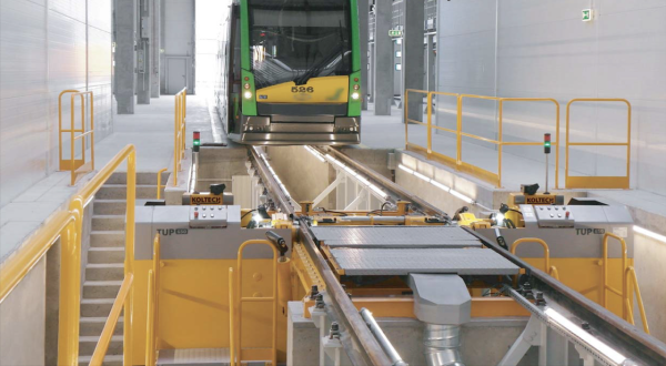
The specific design of the machine allows not only the processing of a wheel set, but also the processing of wheel sets assembled with a wheeled bogie, with gearboxes or motors installed on it. Loading and unloading of the machine can be carried out at floor level on the front side of the machine, where the control panel and the operator’s place are located, through which the complete monitoring of the machining process is carried out.
The processing of railway wheel sets on wheel lathes of the TUU type has the following advantages:
– multifunctionality of the machine;
– low cost of wheelset processing;
– low cost of the tool used;
– ease of application of new design solutions, applied
wash for the process of replacing and installing the cutting tool;
– simple, reliable design of the tool fastening, providing, if necessary, its quick replacement;
– the possibility of processing different profiles with the same tool.
Application of modern technology
The design of the machine uses modern technical solutions developed as a result of many years of practice in the design of machine tools, of which the following are worth noting:
– Application of CNC system manufactured by SIEMENS.
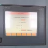
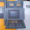
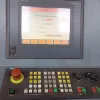
– The use of a tactile control panel along with screens that greatly facilitate training and maintenance of the machine.
– The use of digital control of the drive motors of the calipers, located in one CNC housing.
– The use of brushless motors SERVO AC from SIEMENS, which are the drive motors of the calipers.
– Using the input-output device (PLC) in the working state of the machine based on the PROFIBUS control panel.
– Implementation of a dialogue with the operator, in accordance with the requirements of the philosophy of machine maintenance “human-friendly machine interface” (HMI), which allows you to control the machine in real-time
Standard Equipment
TUU type wheel lathe as standard:
Technological programming for
processing of standard profiles; Device for automatic
positioning of calipers;
Slip Prevention System
drive rollers;
SIEMENS telecommunications modem
for remote maintenance of the machine with
tactile remote control;
Foundation equipment
Exploitation drive motors together with
units of achievement
Completely built-in machine Cutting tools for
final acceptance needs Half-centers 90o
Floor with rails
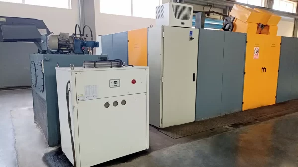
Electrical cabinet with equipment
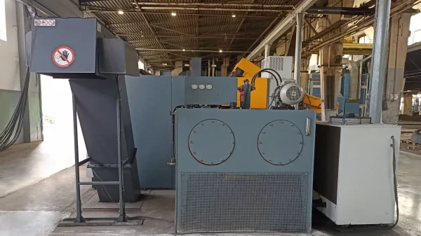
Hydraulic unit with hydraulic equipment Cooler for oil
Measuring heads
Technical documentation
Consecration of the cutting area
Diagnosis of violations in the operation of the machine
system
Exemplary wheelset
SIEMENS telecommunications modem
for remote service
Cameras for instrument observations during
turning time
Additionally, the machine can be equipped
Caliper for processing brake discs and axle elements;
Tool holder for processing rings and processing for balancing wheelset;
Extraction of dust with wires and nozzles,
Half centers 60o
Chip removal system (mechanical
chip conveyor, crusher for
sruzhki, two containers for chips)
Wheel set rotator
What is CNC Above Floor Wheel Lathe?
A CNC above floor wheel lathe is a specialized machine used for the maintenance and repair of railway train wheels. It is called “above floor” because it is designed to be installed on the tracks, above the rails, rather than being positioned at ground level.
The CNC above floor wheel lathe utilizes computer numerical control (CNC) technology, which means it is automated and programmable, allowing for precise and efficient machining operations. The lathe is specifically designed to re-profile and turn the wheel treads, removing any imperfections and restoring them to their original shape.
Here are some key features and functions of a CNC above floor wheel lathe:
Wheel Turning: The primary function of the lathe is to turn the train wheels. It uses cutting tools to remove material from the wheel tread, eliminating any flat spots, wear, or irregularities that may have developed over time. This process helps to restore the wheel’s geometry, ensuring smooth and safe operation.
Precision Machining: The CNC technology enables high precision and accuracy in the machining process. The lathe can be programmed to follow specific profiles and dimensions, ensuring consistent and uniform results across multiple wheels.
Automatic Operation: Once the lathe is programmed with the desired specifications, it can operate automatically without constant manual intervention. This saves time and reduces the risk of human error.
Measurement and Inspection: The lathe may incorporate measurement and inspection systems to assess the condition of the wheel before and after turning. These systems can detect deviations from desired specifications and provide feedback for quality control purposes.
Dust Extraction: As the lathe cuts and removes material from the wheel tread, dust and debris are generated. A dust extraction system is often integrated into the lathe to minimize the release of particles into the environment and maintain a clean working area.
CNC above floor wheel lathes are commonly used in railway maintenance depots or specialized facilities dedicated to wheel maintenance. They play a vital role in ensuring the safety and reliability of train wheels by restoring their optimal shape and surface condition, thereby prolonging their lifespan and improving overall performance. a dialog box supported by a graphical display on the monitor of a running production run.
– Use of the technological cycle of QUICK LIFT FROM THE PROCESSED SURFACE, which allows a quick interruption of the profile processing process in case of damage or foreign inclusions in the processing zone and automatic return to the point where the processing was interrupted after removing foreign inclusions from the processing zone.
– The use of needle bearings designed specifically for heavy-duty designs in roller-guided calipers.
– Possibility of connecting the machine to a computer network and translation of control system data to external databases or storage of data in a database located in the machine.
– Possibility to print the report using a local or network printer, – Remote access to the machine database.
– The use of drive rollers on the machine, equipped as drive ones with hydraulic motors, which are distinguished by their simple design, allowing you to change the speed of each roller while constantly monitoring the uniform distribution of the rotation force.
– The possibility of using a measuring system (measuring heads) on a wheel lathe that performs the functions of positioning the caliper in relation to the wheel pair, measuring the wheel diameter, measuring the height and thickness of the flange; measurement of places of damage to the surface of the processing, transfer and input of data for calculating the depth of cut, with the determination of the diameter of the wheel after processing and proposals for the geometry of the wheel profile.

