Description
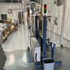
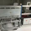
Vertical Inline Vacuum Deposition System
Max 500mm Tall x 1000mm Long Uniform Deposition
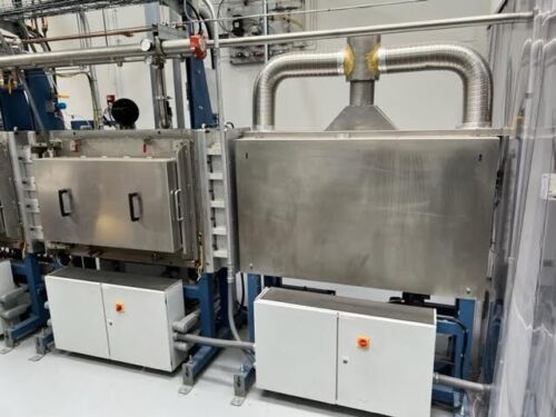
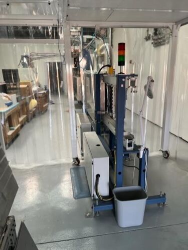
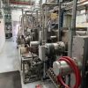
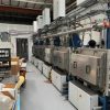
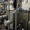
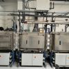
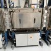
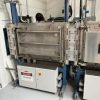
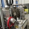
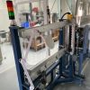
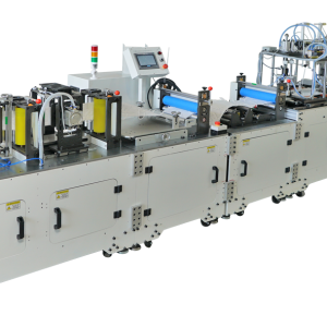
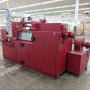
Pilot production vertical vacuum deposition system. System was completely updated in 2019 including controls and software. Currently set up for linear PECVD coating. Process chambers are designed origninally for rotary magnetron sputter cathodes (2 cathodes per process chamber). Substrates are mounted in vertically supported carriers. Carriers move from an external conveyor station, into an Entry Lock, through the vacuum chambers and then to another external conveyor after the Exit Lock. The system has two process chambers can be outfitted with sputter magnetrons or other deposition technology. The system design allows for rapid testing and prototyping as well as pilot production.
Summary of Features
Carrier dimensions: 500mm high x 1000mm long
Maximum uniform deposition zone: Vertically up to 500mm. Vertical uniformity depends upon deposition source design, shielding configuration and gas distribution.
Uniformity horizontally, in direction of carrier travel, is the full carrier length. Carriers move continuously past the deposition sources in the process zones.
Load lock cycle time: 1 minute load to load
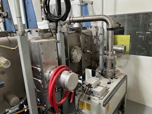
Process Chambers: 2 process chambers. Each can support 2 deposition cathodes (e.g. 1 pair of AC configured sputter magnetrons). Each Process Chamber has an ISO250 gate valve and turbo molecular pump (TMP).
Vacuum Chambers: All stainless steel construction of vacuum wetted surfaces. Two lock chambers, two buffer chambers and two process chambers. Gate valves isolate the lock chambers from atmosphere and from the buffer chambers (4 total gate valves)
External conveyors for loading and unloading carriers plus pre-heat station before Entry Lock Chamber
All utility systems are included: Supply and return cooling water, compressed air, process gas delivery.
Electrical Controls: Allen Bradley control system and HMI
Vacuum Chamber Assembly
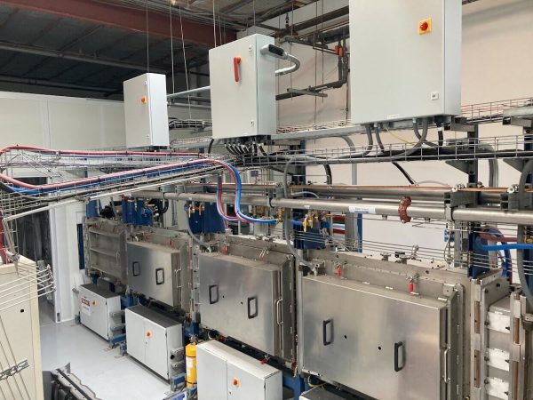
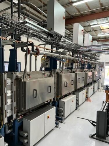
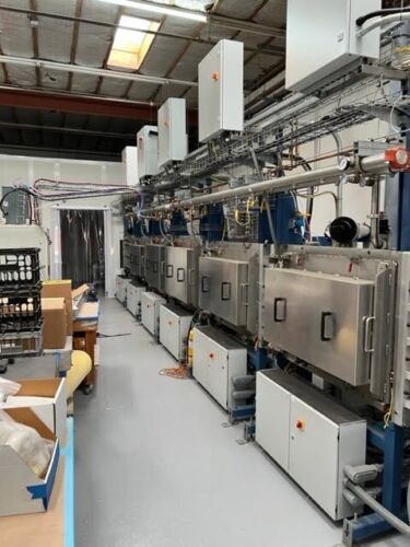
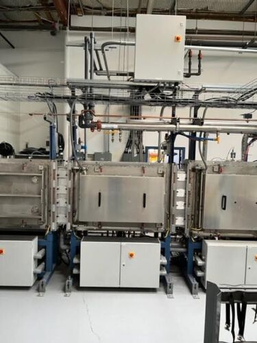
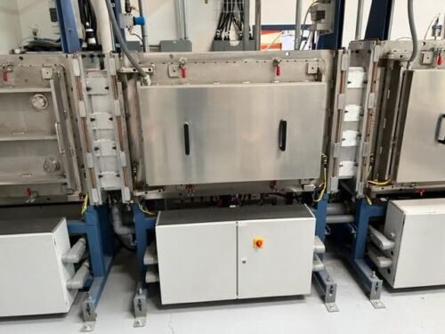
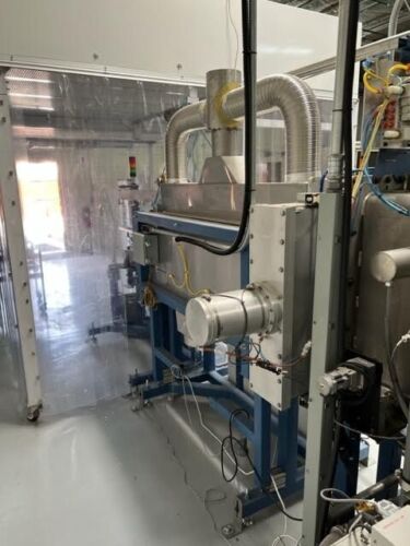
The vacuum chambers are configured inline. Load/Entry Lock, Entry Buffer, Process Chamber 1 Process Chamber 2, Exit Buffer, Unload/Exit Lock
All vacuum wetted surfaces are stainless steel including chamber and door
Chambers are supported on mild steel painted frames.
Electrical control boxes are below the chamber for easy access. All power distribution and I/O are local to each chamber.
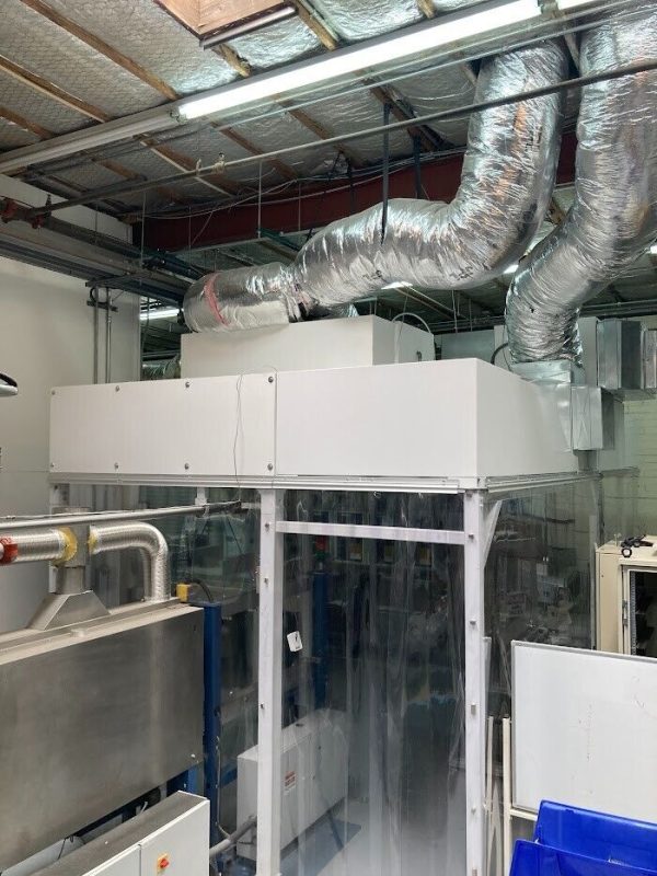
Water, air and N2 utilities are distributed across the top of the chambers.
Enclosures above the chambers house the mass flow controllers
Roughing and TMP backing vacuum
Internal conveyor module in each chamber
Substrate heating system up to Exit Buffer Chamber
Entry Lock Chamber
Pump down from atmosphere to 50mTorr before moving carrier to Entry Buffer
Substrate heating to 200C
Entry Buffer Chamber
Isolated by gate valves from Entry Lock and Process 1
Pumped to high vacuum by ISO250 TMP with gate valve
Cold cathode and Convectron vacuum gauges
Back fill MFC’s to stabilize gas before opening gate valve to Process Chamber
Substrate heating to 200C
Process Chambers
Two Process Chambers with conductance limiting tunnel between them
Dual sputter cathodes can be mounted in each chamber or other source technology. Currently one Process Chamber (PC) has a linear ion source for substrate cleaning installed and linear PECVD deposition sources in the 2 nd PC.
Each PC has an ISO250 TMP with gate valve
Extensive process gas delivery system for each PC. Binary gas delivery systems in each chamber
Substrate heating to 200C
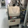
Process chambers have a combined backing pump (Edward IF1800)
Exit Buffer Chamber
Isolated by gate valves from Exit Lock and Process 2
Pumped to high vacuum by ISO250 TMP with gate valve
Cold cathode and Convectron vacuum gauges
Back fill MFC’s to stabilize gas before opening gate valve to Process Chamber
Substrate heating to 200C
Exit Lock Chamber
Transport from Exit Buffer, vent to atmosphere then move carrier to external unload station
Pumping system similar to Entry Lock.
No substrate heating
External Conveyors
Outside vacuum substrates are loaded into carriers on an External Load Station. This conveyor is housed in a small portable clean room (included in sale). Controls are supplied to initiate transport of the carrier into the Pre-Heat Station
Carriers and substrates are pre-heated outside vacuum in a Pre-Heat Station. This station is between the External Load Station and the Entry Lock Chamber. Heating up to 100C is done at this station.
Carriers exiting the Exit Lock move onto an external conveyor similar to the entry external conveyor. Substrates are unloaded from carriers at this station. A carrier storage cart holds empty carriers for transport back to the entry side.
Description of System Components
Vacuum System
Entry and Exit Lock chamber have one rough pump package each (Edwards IF1800)
Roughing is accomplished through 100mm angle valves.
Buffer chambers (2) have one ISO250 Turbomolecular Pumps (TMP) (Adixen ATH2300M).
Process chambers have one ISO250 Turbomolecular Pumps (TMP) each (Osaka iG2204MB).
ISO250 gate valve isolation for all TMP’s are VAT series 110 aluminum gate valves
TMP backing mechanical pump and blower package (Edwards IF1800)
All vacuum piping is thin wall stainless steel tube with ISO or KF style flanges
Formed bellows isolate the vacuum blowers from upstream piping for both the rough and TMP backing pump packages
Electrical plugs are included for all pump electrical connections to ease pump removal.
Vacuum Gauging
Convectron gauges to monitor the piping and chamber pressures from atmosphere to the 10-3Torr range.
MKS type 903 cold cathode gauges measure high vacuum in the Buffer and Process chambers (3 total).
Precise Process chamber vacuum is measured by MKS capacitance manometers (CM). A total of 2 CM’s with isolation valves are supplied.
MKS Atmospheric Pressure Switches on each Lock chamber (2 total).
Slit Valves
A total of 4 slit valves are supplied, two (2) external and two (2) internal. Valves are pneumatically controlled using solenoid valves and have both open and closed limit switches.
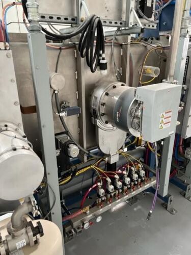
Air actuators are used for control.
Process Gas System
Each Process Chamber is supplied by a total of 8 MFC’s of various sizes
Binary gas flow manifolds are installed in each PC for uniform gas delivery.
Each Process Gas line is fitted with a High Pressure Switch, Low Pressure Regulator, Low Pressure Switch, MFC and Isolation Valves.
The gas components are wired into the PLC and control is executed in the PLC.
Nupro pneumatic and manual bellows sealed valves.
Air System
SMC pneumatic valve manifolds for all pneumatic valves.
SMC pressure switch for protection.
Pressure gauge installed.
Solenoid banks have quick dump valves for ease of maintenance.
Water System
The water system supplies cooling water to the chamber slit valves, turbo pumps, deposition sources, and mechanical pumps and power supplies. Features of the water system include:
Water supply and return headers run the length of the chambers. The headers are mounted above the chambers.
Water flow switches and valves are located on the back of each chamber for ease of access.
SMC type PF3W water flow switches are used to monitor water flow to the PLC.
Visual temperature indication on the return lines of all water circuits.
Main supply and return headers have temperature and pressure gauges.
Supply and return lines are JIC fittings and Parker Push-lok hose.
Heater System
Tubular heating elements with General Plasma’s UltraLok type vacuum penetrations are supplied. All chambers up to and including the Overrun Buffer chamber have substrate heaters.
Radiation and Condensate Shield System
Radiation shields for the heating system and radiation/condensate shields in the process zones are included. Features of these components are:
Radiation shields are a three-layer design. Two thin SS sheets sandwich a thin aluminum sheet. All surfaces are polished. This ‘sandwich’ is riveted together with SS rivets.
Features of this design are:
Excellent thermal blocking performance. The heat flow to the vacuum chamber wall and other ‘cool’ components will be reduced from the current design
Relatively light shield that is easy to install and remove
Internal surfaces remain reflective, while external shield surfaces will be coated over time, the internal surfaces will remain clean so thermal blocking performance remains relatively unchanged.
Shields overlap to avoid gaps and cold spots.
Internal Conveyor System
The carriers are driven from the bottom. The external drive components are accessible from both the back and inside the chamber through the large access doors. Design features of the internal conveyor system are:
GPI designed and built rotary feedthroughs
Allen Bradley Servo Motors with Able Planetary Gear Reducers enabling precise positioning and smooth operation.
Access to all external components of the internal drive system are accessible from the back of the chamber.
Conveyors are easily removed from inside the chamber through the access doors for both preventative maintenance and maintenance.
Carriers are kept inline using a series of guide rollers at the top of the chamber. Carriers
Carriers are a simple aluminum design allowing for easy modification or new designs to be implemented at lower costs.
Carriers can easily be grounded or electrically isolated from the system
External Conveyor System
The functions of the external conveyors are described above in the Coater Overview. Design details of the external conveyor system includes:
External conveyors are similar to the internal conveyors with bottom driven rolls and stabilizing rollers at the top.
Each conveyor includes the conveyor assembly, AC motor, gearbox, motor mounting and protective sheet metal. All electrical and mechanical components are provided.
The heaters, enclosure, controls, etc. is provided for the entry substrate heating
External Conveyor 3 (Preheat Station).
Static control is implemented through an ionizing bar prior to moving carrier to Entry Lock.
Electrical Control System
An Allen Bradley PLC system with a Control Logix processor and A-B Flex I/O. Each chamber will have a remote I/O rack in the electrical enclosure with all I/O associated with that chamber connected to the local rack.
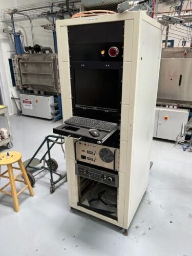
The operator interface includes a 19” color monitor operator interface screens with a PC using an A-B operator interface.
An Allen Bradley Ultra1500 drives with fiber optic communications network for all internal motion axis. The Ultra 1500 drives enable servo positioning and complex motion within the RSLogix ladder logic programming environment.
Smart vacuum gauges with the analog inputs from these gauges are wired to PLC I/O modules.
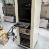
A vertical style console housing the operator interface monitor and PC is included
Each chamber has a separate electrical enclosure containing most of the controls for that particular chamber. This is for the function of both modularity as well as ease in troubleshooting.
Heater Electrical System
Heater controls include circuit protection components, temperature controllers, and thermocouples. All heater wiring. and power distribution is included.
Power Distribution
480VAC/3 Phase/60Hz
Operator Interface and System Software
One PC type computer with monitor are installed in a standup console and are programmed using A-B Factory Talk. Operator Interface Features:
Manual operation of all pumps and valves in the vacuum system with interlocks.
Manual operation of the conveyor drives and process controls with interlocks.
One screen depicting the following:
Vacuum control, status and parameter information. All Vacuum gauge readings are displayed on this screen.
Conveyor drive control, status and parameter information.
Operating parameters and status of all power supplies
Process gas control in the process chambers.
Automated pump down from a cold system
Automated vent from a high vacuum condition
Carrier Tracking: Automatically tracks the position of all carriers on the system at all times and animates them on the HMI screen
Alarm set up, Display and Handling
Trending data and charts: Stores and displays historical data for retrieval and viewing through the HMI

