What is Shell & Tube Heat Exchanger?
Shell & Tube Heat Exchanger – Technical Explanation
A Shell & Tube Heat Exchanger (STHE) is a widely used heat exchanger type designed for efficient heat transfer between two fluids. It consists of a bundle of tubes enclosed within a cylindrical shell, allowing one fluid to flow through the tubes and another to flow over the tubes (inside the shell). This design enables efficient heat exchange between the two fluids without direct contact.
1. Basic Structure & Components
(a) Shell
- A cylindrical outer vessel that contains the tube bundle.
- Provides structural support and allows fluid circulation around the tubes.
(b) Tube Bundle
- Contains multiple tubes where one of the fluids flows.
- Can be arranged in U-tube, straight tube, or floating head configurations.
- Tube material selection depends on thermal conductivity, corrosion resistance, and pressure considerations.
(c) Tube Sheets
- Perforated metal plates that hold the tubes in place at both ends.
- Prevents mixing of the two fluids.
(d) Baffles
- Plates placed inside the shell to direct the shell-side fluid flow.
- Enhances turbulence and heat transfer efficiency while providing mechanical support to the tubes.
(e) Inlet & Outlet Nozzles
- Entry and exit points for the hot and cold fluids.
- Configured for counterflow or parallel flow operation.
2. Working Principle
The heat exchanger operates based on convection and conduction heat transfer principles. The process involves:
Step 1: Fluid Entry & Flow
- One fluid flows inside the tubes (tube-side fluid).
- Another fluid flows in the shell around the tubes (shell-side fluid).
Step 2: Heat Transfer Mechanism
- The hot fluid transfers heat to the tube walls.
- Heat then conducts through the tube material to the cooler fluid.
- The colder fluid absorbs the heat, leading to a temperature rise.
Step 3: Fluid Exit
- The heated or cooled fluid exits through the outlet nozzles.
- The process continues in steady-state operation.
3. Types of Shell & Tube Heat Exchangers
(a) Based on Tube Configuration
- Fixed Tube Sheet Exchanger
- Tubes are welded to the tube sheet.
- Simple design but difficult to clean the shell-side fluid path.
- Floating Head Exchanger
- One end of the tube bundle is free to expand and contract.
- Allows for thermal expansion and easier maintenance.
- U-Tube Exchanger
- Tubes are bent into a U-shape.
- Eliminates thermal stress but is harder to clean internally.
(b) Based on Flow Arrangement
- Parallel Flow
- Both fluids enter from the same side and move in the same direction.
- Less efficient compared to counterflow design.
- Counterflow (Countercurrent)
- Fluids move in opposite directions.
- Higher efficiency due to greater temperature difference over the entire length.
- Crossflow
- Fluids move perpendicular to each other.
- Common in air-cooled applications.
4. Heat Transfer Performance Calculation
The performance of a Shell & Tube Heat Exchanger is analyzed using:
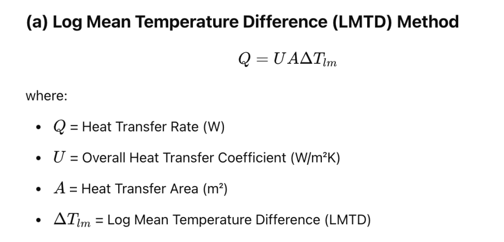
(a) Log Mean Temperature Difference (LMTD) Method
Q=UAΔTlmQ = U A \Delta T_{lm}Q=UAΔTlm
where:
- QQQ = Heat Transfer Rate (W)
- UUU = Overall Heat Transfer Coefficient (W/m²K)
- AAA = Heat Transfer Area (m²)
- ΔTlm\Delta T_{lm}ΔTlm = Log Mean Temperature Difference (LMTD)
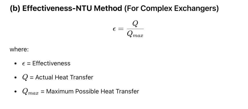
(b) Effectiveness-NTU Method (For Complex Exchangers)

ϵ=QQmax\epsilon = \frac{Q}{Q_{max}}ϵ=QmaxQ
where:
- ϵ\epsilonϵ = Effectiveness
- QQQ = Actual Heat Transfer
- QmaxQ_{max}Qmax = Maximum Possible Heat Transfer
5. Advantages & Disadvantages
Advantages


Disadvantages


6. Applications of Shell & Tube Heat Exchangers


Conclusion
A Shell & Tube Heat Exchanger is a robust, efficient, and widely used heat transfer device in industrial applications. Its modular design, ability to handle high pressures, and versatility make it a preferred choice in process industries, power generation, and HVAC systems. Proper selection depends on heat duty, flow rates, materials, and maintenance considerations.


